USB-C power all the things WiFi edition
My go-to for providing isolated WiFi when playing with IoT devices is an old Buffalo AP. It used a wall wart with a barrel plug connector for power. Those are always somewhat of a pain and rightfully illegal now in the EU, so let’s power it by USB-C instead.
Yes yes, I know the law only actually applies to chargers for small devices and not retroactively. Still my box of tangled up wall warts makes me certainly wish it had an even broader scope and did some time travel.

The access point in question is a 2.4 GHz Buffalo air station WHR-HP-G54 but the basic principle of the conversion applies to a vast number of devices out there.
First you have to check the actual power input of the device. In my case the power supply was 5V at 0.9A. With USB-C this current level would require no special negotiation as 5V is the default voltage. 1.5A and 3A levels are simply signaled by the power supply if available and do not have to be requested.
But what if your device is not 5V or requires even more power?
USB-PD#
These days most USB-C chargers are happy to provide more than just 5V if you ask nicely. USB Power Delivery (USB-PD) is the protocol that makes this happen. It lets devices negotiate voltages up to 48V and currents up to 5A for a maximum of 240W. This extreme amount of power would require the latest Extended Power Range (EPR) specification which is part of USB PD 3.1.
The standard voltage levels required in USB PD 2.0 and later are 5V, 9V, 15V, and 20V. Other non-standard levels like 12V are also somewhat common but not universal. EPR adds options for higher voltages like 28V, 36V, and 48V. A typical 65W laptop charger might offer 5V/3A, 9V/3A, 15V/3A, and 20V/3.25A while a phone charger might only do 5V and 9V.
Better multi-purpose power supplies these days usually also have Programmable Power Supply (PPS) and/or Adjustable Voltage Supply (AVS) protocols available. Those allow for granular voltage control over a given voltage range instead of being limited to fixed voltages. Want exactly 3.3V? 9.6V? Change voltage on-the-fly? If it is in range PPS can make that happen.
With PD-3.0/3.1 with PPS/AVS a charger could, though rarely does, cover all of this and more:

To prevent people from burning down their houses, for anything high-powered (>3A or EPR) USB-PD requires cables to include a so-called E-Mark chip. The chip indicates the cable’s rating to the power supply which must respect it. So if you do not get the expected power level, make sure your cable is actually specified for it.
USB-PD trigger boards#
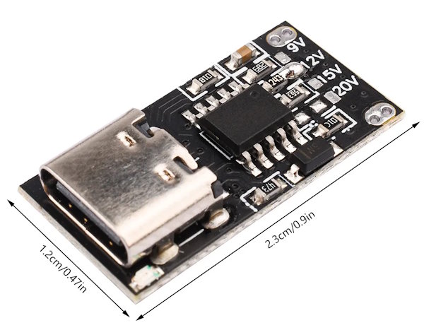
For our purposes we do not need anything fancy. The standard solution is often called USB-PD triggers or decoys. They are pre-built circuits ready to use that allow you to select from standard voltages and handle all the negotiating. Searching Aliexpress for “USB-C trigger” will give you a plethora of options to choose from. I paid 2.24€ delivered for a five pack of these a while ago:
This is so cheap that even for our low power 5V application, there is little reason not to use one.
Annoyingly, many manufacturers of these boards scrub the markings of their chip, but I’m quite sure this board uses a WCH CH224K (or compatible) which is extremely common on these very cheap boards.
According to the datasheet, the CH224K is a “USB PD and Other Fast Charging Protocol Sink Controller” that “integrates multiple fast charging protocols such as USB PD3.0/2.0 … and supports up to 100W power”.
100W with this package? The trick here is that the chip only negotiates the USB-PD and does not itself have to pass any of these watts. Still, I wouldn’t blindly trust 100W to this board. Anyway, in the datasheet you can find almost exactly the same circuit used by the board:

The board is prepopulated with the resistors and you control the output voltage by simply bridging one of the labeled pads to its resistor. The default on my board is 12V.
One thing to be careful about is that these USB-PD triggers will usually pass through any voltage they can get. This means if 12V is not available from the power supply you connected, you might end up with 5V or 9V instead. If your device does not have brown-out detection, this might make it seriously misbehave.
The CH224K has a pin to report “power good” but no one seems to use it. If this is relevant for you, you might have to do some modding or find a board that guarantees to only deliver the voltage you want. Or you make sure to only use power supplies you know/tested can supply the voltage you want I guess ;)
The modification#
The eagle-eyed reader might have already noticed that the labeling on the trigger board only includes 9V, 12V, 15V and 20V. I could spend another euro or two to get a board that directly supports the 5V needed, but where is the fun in that? So the first thing we are going to do is modify the trigger board. There is another way of configuring the CH224K:

Instead of a single resistor on CFG1 it uses CFG1-3 with logic levels to select a specific voltage. If you squint a bit you will see that we can convert our board from resistor to level configuration for 5V by not connecting any of the resistors and instead bridging CFG1 to VDD. A solder bridge from the 9V resistor to the adjacent IC pin will do the trick. CFG2 and CFG3 are already floating so we end up with a 5V request voltage.

Now we can connect the positive and negative output of the trigger board with the barrel plug connector pins.

After re-checking polarity once or thrice it is time to check whether the device works as intended. It did for me so it was time to permanently glue the board into its final position. From the wire length, you might’ve guessed that I found a good position very close to the barrel plug. After removing some plastic with pliers and a file, the board fit right in:

I sticky taped the board to the RJ45 next to it and added a decent amount of hot glue afterwards (not shown here to keep this SFW). With the case closed up again the device almost looks like it was always intended to be this way:

I can now either use the old barrel plug or the USB-C next to it to power the device. I think I already lost the matching wall wart. Oh well.
The result#
I am super happy with the result. Combined with a USB-C Ethernet adapter (more USB-C equals better after all), I have a very handy setup I can throw on my desk when I need it and store away tangle free otherwise.

Standardizing on USB-C power delivery really has been one of the more noticeable technical improvements for me in recent years. Phone, laptop, bike light, soldering iron, old devices created before USB-C even existed, all powered by the same USB-C power supplies I strategically placed everywhere.
Right now the most extreme USB-C PD you could get tops out at 240W. Not quite enough to quick charge your electric car yet but the days of classic power outlets and travel adapters are clearly numbered: USB-C all the things!!11